3D Printing with PETG: Optimizing Thermal Settings for IoT Cases
Introduction: The Thermodynamics of Reliability
Imagine this scenario: You have designed a custom enclosure for a LoRaWAN gateway destined for an industrial attic space. The electronics generate 15 watts of waste heat, and the ambient temperature in the attic fluctuates between 10°C in winter and 60°C in summer. You print the prototype in PLA. Two weeks into deployment, the enclosure warps, the seal breaks, and condensation destroys the PCB. You switch to ABS, but the warping forces during printing lift the corners, and the layer adhesion is insufficient to withstand the installation torque.
This is the classic materials engineering deadlock faced by IoT hardware developers. The solution often lies in Polyethylene Terephthalate Glycol-modified (PETG). It offers the chemical resistance and ductility of PBT, the ease of printing of PLA, and a glass transition temperature () that sits comfortably above most aggressive ambient environments. However, PETG is notoriously finicky regarding its thermal window. It is a non-Newtonian fluid that loves to stick to the nozzle and string across travel moves if the rheology isn't perfectly managed.
In this technical deep dive, we are moving beyond the "slicer defaults." We will examine the applied physics of polymer melt flow, the heat transfer equations that govern layer bonding, and the G-code manipulation required to optimize PETG for high-stress IoT applications. We aren't just printing plastic; we are managing a complex thermodynamic phase change to ensure structural integrity.
Theoretical Foundation: Rheology and Inter-Layer Diffusion
To optimize PETG, one must understand what happens at the molecular level during the extrusion process. We are dealing with an amorphous thermoplastic. Unlike semi-crystalline polymers (like pure PET or Nylon), the glycol modification in PETG disrupts the crystalline structure, preventing the material from crystallizing as it cools. This results in a material that is optically clear and less prone to shrinkage, but it also fundamentally alters the viscosity curve.
The Physics of Layer Bonding
The strength of a 3D printed part in the Z-axis is governed by the diffusion of polymer chains across the interface of two adjacent layers. This process is described by the reptation theory (formulated by Pierre-Gilles de Gennes). The time required for a polymer chain to diffuse out of its initial tube and entangle with the layer below is the reptation time, . This is heavily dependent on temperature.
The diffusion coefficient follows an Arrhenius-type dependence on temperature:
Where:
- is the activation energy of diffusion.
- is the universal gas constant.
- is the absolute temperature.
For IoT cases, we need maximum to ensure the case is watertight. This implies printing at the highest possible temperature before thermal degradation occurs. However, we are fighting against gravity and viscosity. If is too high, the viscosity drops too low, leading to poor dimensional accuracy (oozing).
Heat Transfer Modeling
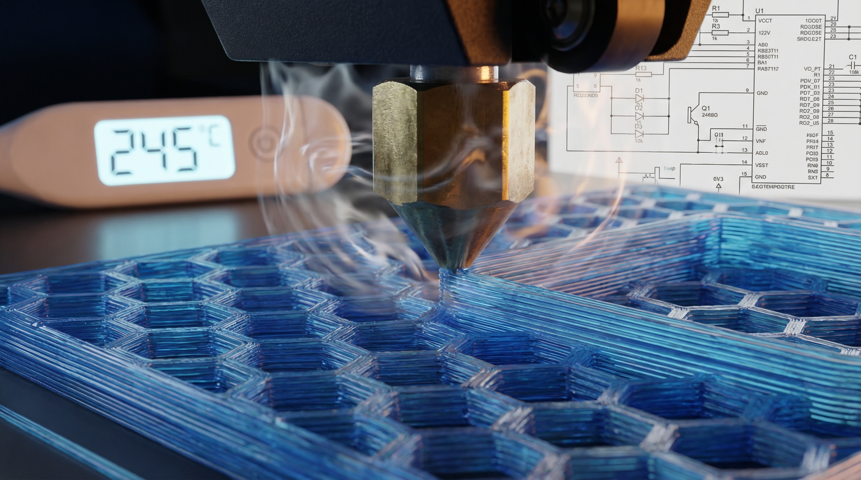
When the hot filament (at nozzle temperature ) is deposited onto the previous layer (at surface temperature ), the cooling rate is governed by Fourier’s Law of Heat Conduction and Newton’s Law of Cooling. The temperature distribution can be approximated by the heat equation:
abla^2 T$$ Where $\\rho$ is density, $c_p$ is specific heat capacity, and $k$ is thermal conductivity. **The Engineering Challenge:** PETG has a relatively low thermal conductivity (~0.29 W/m·K) compared to the rate at which we extrude it. This means heat tends to stay localized. If you print small IoT features (like screw bosses) too fast, the local area never drops below $T_g$ (approx. 80°C), and the feature turns into a shapeless blob. Conversely, if you cool it too aggressively with fans, you halt the polymer chain diffusion (Reptation) prematurely, resulting in a brittle part that will crack when you tighten the enclosure screws. # Implementation Deep Dive: G-Code and Thermal Logic Theory implies we need a "Goldilocks" zone: hot enough for diffusion, cool enough for dimensional stability. Standard slicers often fail to account for the specific thermal mass of IoT enclosures. We will intervene directly with G-code. Below are specific implementation strategies for Marlin-based firmware (common in Prusa, Creality, etc.). ### 1. The Pre-Heat Soak (Minimizing Warp) PETG expands thermally. If you start printing the moment the bed hits 80°C, the glass/PEI sheet hasn't reached thermal equilibrium. This leads to first-layer shifts. We use a G-code macro to enforce a soak time. ```gcode ; --- PETG Thermal Soak Routine --- ; Designed for IoT Case Flatness Assurance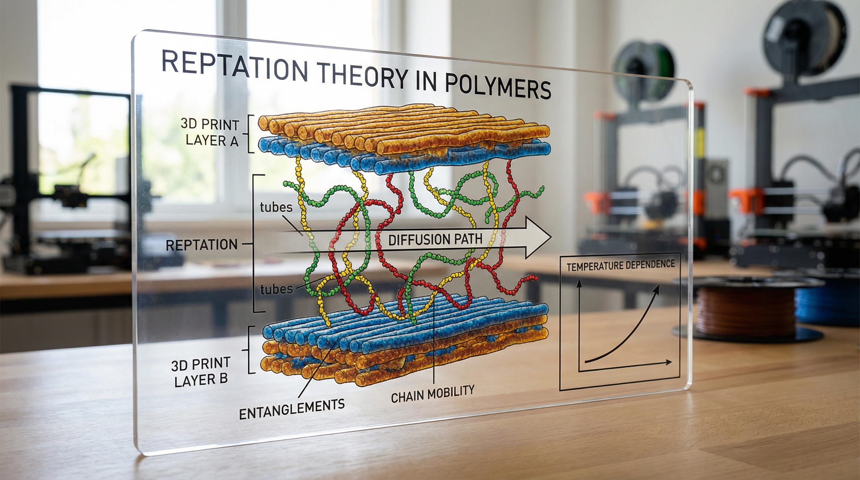
M140 S80 ; Set Bed Temperature to 80C (No Wait) M104 S160 ; Set Nozzle to non-ooze temp (160C)
; Wait for Bed to reach target M190 S80
; DWELL command for thermal equilibrium ; G4 P[milliseconds]. P300000 = 5 minutes M117 Soaking Thermal Mass... G4 P300000
M104 S240 ; Now heat nozzle to printing temp M109 S240 ; Wait for nozzle
; Prime Line (High flow to clear heat creep) G1 X0.1 Y20 Z0.3 F5000.0 ; Move to start position G1 X0.1 Y200.0 Z0.3 F1500.0 E15 ; Draw the first line G1 X0.4 Y200.0 Z0.3 F5000.0 ; Move to side G1 X0.4 Y20 Z0.3 F1500.0 E30 ; Draw the second line
**Analysis:** The `G4` command is critical. It allows the heat from the bed heater to conduct through the build plate substrate, ensuring the surface is actually at 80°C, not just the thermistor on the bottom.

### 2. Dynamic Fan Speed for Layer Bonding

For an IoT case, the walls need to be strong (low cooling), but the bridging (top of the case) needs to be pretty (high cooling). PETG binds instantly to itself if no fan is used. We can script dynamic fan speeds based on feature type.

```gcode
; --- Dynamic Cooling Logic ---

; LAYER: Walls (Maximize Strength)
; Fan set to 30% to allow polymer diffusion time
M106 S76 ; 30% of 255 = ~76

; ... printing perimeter instructions ...

; LAYER: Bridge/Overhang (Maximize Dimensional Accuracy)
; Rapid cooling needed to freeze melt in mid-air
M106 S255 ; 100% Fan
; ... printing bridge instructions ...
; RETURN to Wall settings immediately after bridge M106 S76
**Logic:** Most slicers do this automatically, but they often set the "Min Fan Speed" too high for PETG. For maximum waterproofing, you want the fan at 0-20% for the walls. High fan speeds on perimeters are the #1 cause of delamination in PETG enclosures.
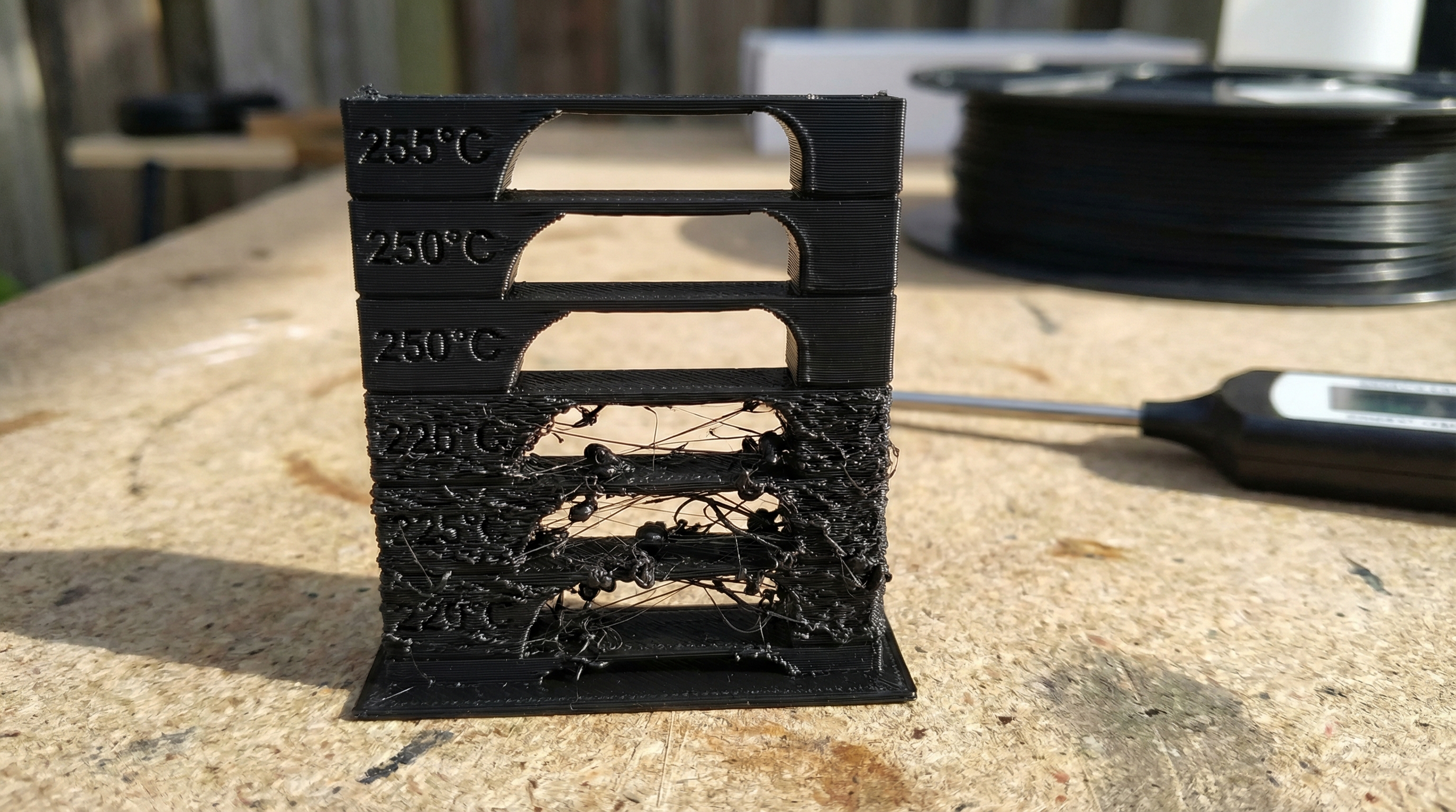
### 3. The Temperature Tower (Finding the Sweet Spot)
To find the optimal temperature for your specific brand of PETG, you don't guess; you test. Here is a snippet logic for a temperature tower that changes temp every 50 layers.
```gcode
; --- Variable Temperature Logic ---
; Layer 0-49: 250C
; ... printing ...
; Layer 50 Trigger
M117 Temp 245C
M104 S245 ; Set target, don't wait (flow keeps moving)
; Note: We don't use M109 here because stopping causes a blob.
; Layer 100 Trigger
M117 Temp 240C
M104 S240
; Layer 150 Trigger
M117 Temp 235C
M104 S235
Performance Consideration: When changing temperatures mid-print (M104), there is a lag. The PID controller of the hotend needs time to settle. Do not change temps on a layer that contains critical fine details (like screw threads). Plan the tower so changes happen on straight walls.
4. Linear Advance Tuning for Watertight Corners
IoT cases need sharp corners to fit PCBs. Standard extrusion over-extrudes at corners due to nozzle pressure. We need K-factor tuning (Linear Advance).
; --- Linear Advance Configuration ---
; Value must be calibrated experimentally for PETG
; PETG acts like a spring, requiring higher K values than PLA

M900 K0.08 ; Set Linear Advance K-factor

; If running Klipper firmware, the syntax is different:
; SET_PRESSURE_ADVANCE ADVANCE=0.08
Without this, the pressure built up in the Bowden tube or extruder gear continues to push plastic out even as the print head slows down for a corner, creating a bulge. That bulge prevents the lid of your IoT case from closing tightly.
Advanced Techniques & Optimization
Once the foundational G-code is established, we move to elite-level optimization strategies specific to PETG's material properties.
1. Minimizing Hydrolysis (The Moisture Problem)
PETG is hygroscopic. It absorbs water from the air. When heated to 240°C, that water boils, creating microscopic steam pockets inside the filament. This is hydrolysis, and it breaks the polymer chains, reducing molecular weight and structural strength.
- Optimization: You cannot optimize print settings to fix wet filament. The material must be dried at 65°C for 6 hours prior to printing. If you hear popping/crackling, your print is already compromised.
2. Retraction Tuning and Hysteresis
PETG is "stringy" because of its high ductility and surface tension in the melt phase. Aggressive retraction (pulling filament back) often causes clogs because the soft PETG deforms in the extruder gears.
- Strategy: Instead of long retractions (e.g., 6mm), use faster, shorter retractions (e.g., 3mm at 45mm/s) combined with a "Travel Speed" increase. Moving the head faster between print moves (200mm/s+) breaks the string of molten plastic physically, rather than relying solely on suction.
3. Variable Layer Height for IoT Enclosures
For an IoT case, the vertical walls can be printed at thick layers (0.3mm) for strength and speed. However, the top and bottom surfaces, and any snap-fit overhangs, benefit from thinner layers (0.15mm).
- Technique: Use "Adaptive Layers" in your slicer. Thicker layers retain heat longer, improving the (diffusion) from our Arrhenius equation, resulting in a stronger chassis body.
4. Avoiding the "Blob of Death"
PETG loves to stick to the nozzle. If the nozzle picks up a small strand of filament, it will accumulate, brown (burn), and eventually drop onto your print as a black, carbonized chunk.
- Fix: Apply a non-stick coating to the nozzle (Nickel-plated copper or Tungsten Disulfide) or use a silicone sock. This is mandatory for long IoT case prints.
Real-World Applications
Where is this level of optimization actually necessary?
Industrial Sensor Arrays
I recently worked on a project involving vibration sensors for mining equipment. The cases had to withstand constant vibration and ambient temps of 50°C. PLA would soften; ABS would delaminate under vibration. By optimizing PETG settings (high temp 250°C, low fan 20%), we achieved a case that survived the "drop test" from 2 meters onto concrete—a feat impossible with standard profiles.
Outdoor Agricultural LoRa Nodes
For smart agriculture, devices sit in direct sunlight. UV radiation degrades many plastics. Black PETG has reasonable UV resistance. We utilized the watertight geometry techniques (Linear Advance + High Flow overlap) to create IP67-rated enclosures without gaskets, relying purely on the interference fit of the printed plastic, saving $0.50 per unit in BOM costs.
Custom Server Rack Mounts
In data centers, airflow is king. Custom baffles and brackets printed in PETG can withstand the exhaust heat of servers (often reaching 40-50°C) without creeping (slowly deforming under load) over months, provided the wall thickness and infill patterns are optimized for the specific load vectors.
External Reference & Video Content
In the associated video "3D Printing Optimization," the presenter discusses the concept of the "Iterative Feedback Loop." This aligns perfectly with our approach to PETG. The video highlights how visual artifacts are often symptoms of underlying physics issues—for example, describing how "ringing" or "ghosting" is a vibration frequency issue, similar to how we treat rheological flow issues.
While the video covers general optimization (including mechanical tightening and PID tuning), it serves as a prerequisite to this article. You cannot achieve the thermal precision required for PETG if your PID controller is oscillating or your belts are loose. The video's section on Flow Rate Calibration is particularly relevant; for watertight PETG IoT cases, we often deliberately over-extrude the internal solid infill by 2-3% (Flow multiplier 1.03) to ensure zero gaps, a technique that requires the stable mechanics demonstrated in the video.
Conclusion & Next Steps
Printing PETG for functional, industrial IoT applications is not about hitting "Slice" and walking away. It is an exercise in applied physics. We have explored how the glass transition temperature dictates our thermal floor, how the Arrhenius equation drives our need for heat to ensure layer diffusion, and how specific G-code commands like M104, G4 dwell, and M900 linear advance allow us to manipulate these variables.
Key Takeaways:
- Heat is the Glue: Maximize temperature and minimize cooling for strength, constrained only by print geometry.
- Soak the Bed: Use
G4to ensure the build plate is thermally stable to prevent warping. - Tune the Flow: Use Linear Advance to manage nozzle pressure for watertight corners.
- Dry Your Filament: Hydrolysis is the enemy of structural integrity.
Next Steps: I recommend generating a custom temperature tower ranging from 230°C to 260°C with the G-code logic provided above. Break the resulting blocks. The temperature that forces you to use pliers to break the layer bond is your new production standard. Stop printing prototypes; start manufacturing engineering components.